https://www.stangnet.com/mustang-forums/threads/foxbody-nuts-bolts-screw-list-temp-sticky.893778/#js-post-9004183
Engine Related:
Fan Pulley on the water pump 5/16-24 x ¾” with lock washers
Fan to Fan Clutch 5/16 X 18 X ½” with lock washers
Water pump bolt with treaded stud 5/16” X 18 ----3/8” X16 length 3-7/16” and 5”
Intake bolts =Lower intake to head.... 5/16 X 18 X 2" they are all the same.
Upper Intake to Lower Intake =4 corner bolts are 5/16 x 1 5/8 and the 2 middle bolts are 5/16 x 6. Size and Thread pitch 5/16-18 in.
Smog in back of head /Thermactor Plug5/8-11
External thread is 5/8 x 11Internal thread is 7/16 x 14
Or if you rather put a plate over that hole instead of the Thermactor Plug the threaded hole beside it uses a 7/16-14 bolt.
OR----5/8-11 x 3/4" bolts
Bolt that goes thru cross over pipe into back of heads= 5/16" x 1 1/2" course thread.
SPARK Plug Thread.. 14mm x 1.25
2 Different Head bolt lengths--- ARP’sare 3-15/16" and 2-7/16"
Head Bolt --- 7/16 by 14.
Header Stud Bolt at Collector—Stock—7/16 X 14 pitch Total length 2-3/4” under stud length 2”
90-95
M12 x 1-3/4 - 7/16 x 70m Ford part #N804013-S2
Crankshaft Bolt/Harmonic Balancer 5/8 with 18 pitch thread, RH
Holds Balancer to Crank Shaft) 15/16” Socket --- 24 mm works also.
4 Crank Pulley bolts are ------3/8-16 x 1"
Low Oil Sensor Plug-----20mm 1.5 thread pitch
Ignition Module = (5.5mm) Deep Thin Wall ¼” drive
Or? the TFI module bolt is M4 x 10mm screw. The stock ones have a 6mm hex head with an 8mm (OD) washer under the head. The bore diameter in the TFI plastic housing is 9mm.
Oil Pan SOCKET--- 9/16” 6 point
Oil Pan Plug -----1/2 X 20 MM
Oil Pan to Block---- 18 bolts ¼”- 20 x 7/16"--- 4 bolts 5/16"- 18 x 9/16"
Oil pump- 3/8" -16 x 1"
Oil pickup tube - 5/16" -18 x .75"
Header Bolts at block --- (stock) 3/8" x 16 x ¾”
H pipe to Catback stock--- 7/16 – 14
Fuel Rail bolts= 1/4 - 20 X 3/4"
Tensioner Pulley Bolt= left hand thread 12mm
Tensioner Pulley Nut =left handed thread18mm socket/wrench
Throttle Cable to Bracket =… 9 mm screw
Valve Cover bolts =¼ x 20 x 1”
Starter bolt =… 3/8 -16 X 1.5
TFI module 6-32 x3/4" common screw
O2 bung plug size= 18mm
Oxygen Sensor Thread Size=-- 18mm x 1.5
Schrader Valve thread pitch= 1/16 NPT
as per the autometer website:
model #3275
1/16" NPTF Male to -4AN
Male mechanical gauge adapter for fuel rail
model #3280
1/16" NPTF Male to 1/8" NPT
Female adapter for fuel rail
For use with Electric Fuel Pressure gauges
TPS = M4 x 0.70 pitch x 25mm length - Phillips Pan Head
Stock Intake Torx Head Plaque screws = 8-32 x .62 taper seat machine screw
IAC= Flanged head M 6 X 1.0 X 25mm
T-stat housing bolts= 5/16-18 x 1 3/4" for top left bolt
5/16-18 x 1 1/4" for bottom right bolt, both bolts use split lock washers.
CAMSHAFT Thrust Plate/ could also be called retainer plate= 1/4X20 X 3/4”
CAM Bolt = 3/8 X 16 x 1 ½-- washer thickness 7/32
EFI fuel rail = 1/4" -20 x .75"
Distributor hold down = 5/16" -18 x .75"
Motor Mount to Block--- 7/16" x 14 x 7/8”
Motor Mount Nut 14mm x 2.0 (pitch)
Sensors on Intake --- 3/8" NPT
Flywheel bolts 7/16-20 thread.
Thermostat housing Trick flow Track heat intake= 5/16-18 there are 2 bolts (1) bolt 1” (the other) 1-1/ 2”
Radiator Bracket Bolt = Metric8 x1.25
Alternator Bracket Bolts
Quantity 2: Alternator Bracket to block 3/8-16x2”
Quantity 1: Alternator Bracket to head 7/16-14x1-3/4”
7/16-14 x5" (goes front-to-back, lower outer hole), also needs compression sleeve in the front hole.
3/8-16 x1 1/4" (bolt reversed… goes back-to-front, upper inner hole)
Suspension Related
All the control arm bolts and nuts are 18 mm. The shock bolt head is 15 mm and the nut is 18 mm. The sway bar bolts are 15 mm. The drive shaft bolts are 12 mm 12 point.
Drive shaft bolts--- 12 pt 12 mm X 1”
Rear Diff cover=--Stock5/16 X18 X3/4” … w/ TA cover X 1-1/4 long
Bearing Cap bolt--- 1/2-13
Lower STRUT NUTS=--- Upper is 13/16” Bottom is 21mm 24mm if they're stock.
TOP STRUT NUT OEM ----- M16 x 2.00
Rear Shock (axle housing mounting bolts) =-- 12mm x 1.75 x 70mm or you can use a 1/2" x 1.50" long bolt.
Quad shock axle housing mounting bolts(12mm x 1.75 x 70mm)
Rear shock axle housing mounting bolts(12mm x 1.75 x 70mm)
Upper control arm axle housing bolts(12mm x 1.75 x 80mm)
Lower control arm axle housing bolts(12mm x 1.75 x 100mm)
Front Lower Control Arms 16mm X 4-5/8” socket =-- 21 mm on the bolts and a 24mm on the nuts.
Rear Lower Control Arms 16 mm x 4”
Bolt size = 12mm
Length from bottom of flange = 4 inches
Threads length = 1 7/8 inches
Head size = 18mm
High strength - Class = 10.9
K Member Bolts
4ea M-14 2.0 Pitch x 95mm
4ea M-12 1.75 Pitch x 25mm class 10.9
Jam Nuts on Tie Rod Ends --- 9/16"-18
Ball Joint Castle Nut =---5/8 x 18
Front Wheel Bearing Castle Nut = 1 1/8”
Rear Sway Bar bolt thread size and length= (1991- 1993)M10 x 1.50 x 33mm
Grade 10.9 (1989) 3/8-16 X 1-1/4
Front Sway Bar Bolt= M10 X 1.5 X 38 MM Grade 10.9
Steering rack bolts=5 ½” x ½”
Steering shaft bolt=M10 x 1.0 with 11mm 12 point head and 1.20" under head length
Stock Hood Bolts = M8x1.25x20mm
Tie rod jam nut= 5/8-16 thread.
Outer tie rod castle nut= 1/2X 20
K-Member Bolts = M16 x 2.0 x 117.5
Stock Cotter pin Front Wheel Bearing = 3/16 x 2”
Transmission & Bellhousing Related
Transmissions to Bellhousing ---12mm x 40mm X 1.75 pitch. Ford# N605935-S2
Motor to Bellhousing=--- 7/16 X 14 thread pitch 1.5” for 302/351W
Bellhousing to block bolts are all SAE 7/16-14. The top two are 1 7/8" long and the other 4 are 2 1/4" long.
Transmission Mount to Transmission= 1/2" X 13 X 1-1/2” long.
Bellhousing to spacer plate (block plate) = 5/16 X 18 x 1" long
Clutch Fork Cover Bolt Size----6mm x1.0 with 8.8 Hex Head ( or it's nothing much more than a small course-thread sheet metal screw with an 8mm head).
Shifter Bolt to Trans =- M8 x 1.25 x 20mm.
AOD Shifter nut = M8 x 1.25 X 20MM
Shift knob thread= 12mm x 1.75
Speedometer bolt to Trans T-5=--- 1/4-20 x 3/4". Also has a split ring lock washer
Vehicle Speed Sensor= 1/4 X 20 X 3/4
Thread Pitch for T5 Neutral Safety Switch Hole =16mm x 1.5
Pressure plate bolt =8 mm x 1.25…. (Wrench Dia.13mm)
MISC:
Seat Bolts and Nut= Bracket to floor = M10x1.5 -- Seat to bracket = M8x1.25
Seatbelt – T50 Torx head
Door Striker =-- T50
Door Striker Thread= -- 7/16"-14
Door Hinge Bolt= -- 5/16- 18 pitch X 1 1/4
Rear Hatch Striker = T50
Rear Hatch Striker Thread= 7/16 x 1 thread.
Rear Seat Belt =---T50
Arm rest (under plastic plugs) 6mm x 1.0
Wheel Stud Bolts=---1/2” X 20--- Knurl Diameter—0.615in
Lug Nuts=------1/2”-20 R
Head light adjuster bolt/ screw = 4mm or 5/32
Plastic piece on the male side of the hatch latch OD= 11/16” ID= 1/2"
Airbag bolts M6 x 1.0 x 10mm long
Proportioning valve to the front right brake caliper =7/16-24
Front Bumper Rivets = 3/16”
Door Rivets are 1/4”
Power steering stud size = 7/16-20
Rear License Plate Screw #14 with self cutting threads
¼ Window Nuts= M4 x 0.7
Fuel Tank strap bolt = Head is 13 MM
Hood Latch = M7 X 1.25 X 22.225 ******** 7/8” length
Ground Strap weaved …back of head=3/8 16 X 1/2.
Oil pressure sender extension =1/4 NPT
Throttle Body Studs = 5/16-18 X 4 1/8”
Smog Pump Top 2 bolts to rubber hose to Air Bypass = m6 15mm long
Battery hold down bolt =6mm x 1.0 x 55m
Ground bolt at Timing Cover =3/8 -18 x 1"
Stock Cotter pin Front Wheel Bearing = 3/16 x 2”

Sunday, January 6, 2019
Tuesday, January 1, 2019
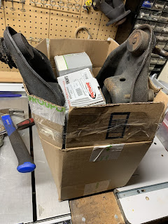
33. Rusty Old Motor
spent the morning pulling off the shroud, radiator, and frint braxkets. Water pump bolts removed without any breaking off in the block, which was pretty fortunate. Lot of corrosion due to installer not using anti seize bolts. More fun!


Monday, December 31, 2018
31. New Top End
I ran across this locally on CL and the price was right, so I picked up the upper and lower intake with fuel rails and an adjustable fuel pressure regulator. I have a set of 24 pound injectors which will work nicely. Should rip once I get it all bolted up
Edelbrock 3820 and 3822 with Aeromotive regulator
New Valve Covers

Current stock 5.0 HO intake/setup (as it currently sits)

Edelbrock 3820 and 3822 with Aeromotive regulator


New Valve Covers

Current stock 5.0 HO intake/setup (as it currently sits)


30. Front End Suspension
The existing front end was pretty rough, so I sent out an extra set of A Arms to get new bushings and ball joints pressed in locally, while I took apart the front end.
There was a lot of rust and debris both in the A Arms and shock tower pockets, so the replacements will work well and the rust areas will get a solid dose of POR 15 to stop the rust from getting any worse. No structural concerns.
The new stuff


Online Resources
Mustang FRONT SPRING REMOVAL
- Jack up your car and support it with jack stands
- Remove the front wheels
- Remove the Sway Bar Endlink nuts and rotate the sway bar out of the way
- Remove the brake caliper bolts
- Slide the caliper off the rotor
- Remove the brake rotor from the hub
- Take off the ABS retainer nut, remove the bolt and ABS sensor
- Support the lower control arm with a floor jack
- Remove the strut nuts and bolts
- Free the spindle from the strut
- Lower the jack to allow the control arm to hang free
- Now you can remove the front Spring
- Install new urethane spring isolators on your new springs
- Install the new spring into the “saddle” on the control arm (pry bar is handy tool)
- Use the jack to raise the control arm
- Install the Caster Camber Plates (highly recommended)
- Remove the upper strut nut
- Remove the front strut
- Use a drill to remove the rivets from the factory camber plate
- Install the bolt plate with the notch facing forward (on underside)
- Drill holes for engine compartment support brace
- Install the bearing plate (follow instructions for proper slot alignment)
- Install retaining nuts
- Reinstall your strut - Now is a good time to replace them if needed
- Install spacer stacks according to included instructions
- Slide the strut shaft through the caster camber plate and tighten the nut
- Slide strut into the spindle and reinstall the strut hardware
- Reassemble the ABS and Brake hardware
- Reattach the Sway bar
- Repeat on other side
REAR SPRING INSTALLATION
- Lift the rear end of the car off the ground
- Remove the wheel
- Support with jack stands
- Remove the rear lower shock bolt
- Apply some downward pressure to the rear end to remove the rear springs
- Install new urethane spring Isolators (recommended)
- Install the new spring with the pigtail facing rearward
- Reinstall shock hardware
- Install the wheel & repeat on other side
Prothane Front Control Arm Bushings Installation
Learned this online:
Poly can be used in the front control arms with minimal increase in harshness and without any squeaking. The key is in the installation. Front poly bushings can induce a lot of harshness because of their design (at least the design of Energy Suspension bushings). The sleeves of the Energy Suspension front control arm bushing are shorter than the bushings. If you install the front bushings as they come, the k-member clamps down on the faces of the bushing when the bolt is tightened. Because the mass of the bushing has to go somewhere, it attempts to expand in the shell. (See Figs. 1 and 2)
The ends of the bushing are now clamped against the k-member and the perimeter of the bushing is pre-loaded in the shell. As a results, the control arm/bushing can't pivot or flex as needed. This is where the majority of complaints of queaks and harshness comes from with poly bushings in the front control arms.
The key to minimizing harshness and elimintating squeaking is to trim the end of the bushings so that the k-member clamps on the sleeve and not the face of each bushing. The end without the flange is the one that is trimmed. I use a hacksaw to trim them. By trimming the bushing, a clearance is provided between the bushing and the k-member (See Fig. 3).
The flange of the front and rear bushings keeps the front arms from moving front-to-rear relative to the k-member. The control arm cannot shift forward because of the flange of the front bushing and it cannot move rearward because of the flange of the rear bushing.
The result of this install technique is no squeaking and a ride that's nearly as smooth as with rubber bushings. I've used this install techique on SVO Mustangs, Fox-Body Mustangs and SN-95 Mustangs with excellent results.
Give it a try! You'll like the results
29. New Rims
I sourced a set of Snyper ROH 16x8 4 lug rims locally, and had them stripped and powder coated locally and they look fantastic. Advanced Powdercoating always does good work.
I just don't have the time or initiative to convert everything over to 5 lug and get access to more rim styles when I already have a set of rims which are extremely light and will look nice with a 2" drop.
Stock 16x7 rims ran a 225/55/16 which was an OD of 25.7". An 8" should have at least a 245 on it, maybe 255.
Looking at 245/45R16 up front and either 245 or 255/45R16 in back. 225 too narrow. I saw online someone posted their target caster camber specs for a lowered 5.0 so added it to my blog as a reminder for when I get everything back together.


27. Refresh Part Two
Round 2 of the "dump car" has begun.
It ran ran really well with a 92 roller motor T5 and manual steering, however the previous owner had stripped it and left it in pieces. I repaired all the rusty floor pans about 5 or 6 years ago and put it back together structurally, but three kids and a career forced me to park it for awhile.
Over the years I have accumulated all sorts of parts for it, including 2" drop eibach springs, MM bumpsteer kit, explorer upper and lower with 65 mm TB, 93 cobra k member and spindles, upper/lower control arms, etc.
The brakes were spongy, so new calipers, rotors, master cyl, booster and stainless lines going on all around this winter and a nice set of 06 Mustang seats for the interior. Needless to say, its been sitting too long in my garage so just about everything is being gone through and either replaced or upgraded.

Wednesday, August 29, 2012
Summary
1986 Mustang GT
Last year of the 4 eyed style front
end before the aero nose of 87-93. Was purchased in pieces and built from floors up. Sound deadener and a fresh
grey and black interior, solid drivetrain, and new Kumho tires on 16” Pony rims.
Starts on the first turn of the key, does not leak oil or smoke. 91 roller
motor with nice lopey idle, has not been converted to Mass Air. (stock SD system)
Prior owner may have installed an upgraded cam.
Interior
Raam Mat Sound Deadening covered with Foil Faced Automotive Batting and new Black Carpet
Raam Mat Sound Deadening covered with Foil Faced Automotive Batting and new Black Carpet
Second Skin Sound Deadener and Foil
Insulation installed on Firewall and Roof
Aftermarket Rally Seats with Console
Delete
New Headliner
Dark Grey OEM Dash Pad
Power Windows (both are working)
Converted to Manual Steering – New Steering Rack
New Windshield
New Headliner
Dark Grey OEM Dash Pad
Power Windows (both are working)
Converted to Manual Steering – New Steering Rack
New Windshield
New Dew Wipes on the outside of the
windows
Tilt Wheel with Functioning Cruise
Control
AM/FM CD Stereo
AM/FM CD Stereo
Weight Reduction:
Entire Heating and AC System removed
Back Seats removed and Hatch
Carpeted, including aluminum panel over spare tire area
Smog System Deleted
Exterior:
Could use fresh paint but currently painted a metallic gunmetal grey.
16” Pony Wheels painted flat black
Kumho 255/50/R16 Tires with a lot of
tread
POR-15 underneath on the floor pans
and chassis
DriveTrain:
91 5.0 Roller Long Block which starts right up on first turn
DriveTrain:
91 5.0 Roller Long Block which starts right up on first turn
Fuel Injected (I went through the
entire system)
Stock hood insulation
T-5 Transmission with Hurst Shifter
T-5 Transmission with Hurst Shifter
Aftermarket clutch quadrant and
adjustable clutch cable
MAC Shorty Headers
MAC Shorty Headers
Flowmaster Exhaust system with H
pipe and Rear Dumps
87-93 Front Disc Brake conversion
with larger rotors and calipers
Rear axle has fresh fluid and
friction modifier, new brake shoes (4 lug) and shocks
Misc:
Had a new fuel tank and fuel pump
installed by prior owner, I installed a new fuel gasket on the filler neck. 87-93
GT sway bar added. New fuel pump relay, fuel filter, hoses and coolant, battery
cables, U Joints.
Sold privately as is, with no warranties or guarantees. Make me an offer.
Subscribe to:
Posts (Atom)